
GM50A/GM51A Metal-sealed 5-50,000 sccm Mass Flow Meters
GM50A/GM51A Metal-sealed 5-50,000 sccm Mass Flow Meters
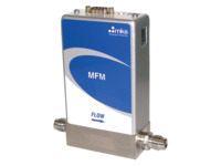
The GM50A and GM51A are general purpose, metal sealed Mass Flow Meters (MFM) well suited for a wide variety of applications requiring flow metering from 5 sccm to 50 slm Full Scale, N2 equivalent. These Meters incorporates the latest in digital flow meter electronics along with a well proven, patented thermal sensor and mechanical design.
The GM50A is 1.45 inches wide.
The GM51A is 1.25 inches wide.
- Embedded user interface to easily change range and gas reduces inventory required
- Monitor and collect device data in-situ
- 16 micro-inch 316L surface finish for high purity applications
- Wide choice of digital or analog I/O See All Features
Configuration Options
The following options are available for GM50A & GM51A Mass Flow Meters
Ordering Code Example: GM50A013502R63020
|
Configuration Option |
Option Code |
|---|---|
Model |
|
| GM50A Mass Flow Meter (1.45 in. wide) | GM50A |
| GM51A Mass Flow Meter (1.25 in. wide) | GM51A |
Gas (Per Semi Standard E52-0703) |
|
| Nitrogen (N2) | 013 |
| Ammonia (NH3) | 029 |
| Sulfur Hexafluoride (SF6) | 110 |
| Additional Gas Options | See Here |
Flow Range Full Scale* |
|
| 5 sccm | 500 |
| 10 sccm | 101 |
| 20 sccm | 201 |
| 50 sccm | 501 |
| 100 sccm | 102 |
| 200 sccm | 202 |
| 500 sccm | 502 |
| 1000 sccm | 103 |
| 2000 sccm | 203 |
| 5000 sccm | 503 |
| 10000 sccm | 104 |
| 20000 sccm | 204 |
| 30000 sccm | 304 |
| 50000 sccm | 504 |
Fittings (compatible with) |
|
| 6 mm Swagelok | M |
| 8 mm Swagelok | E |
| 10 mm Swagelok | P |
| 12 mm Swagelok | F |
| 1/8 in. Swagelok (1000 sccm or below) | A |
| 1/4 in. Swagelok | S |
| 1/2 in. Swagelok | K |
| 3/8 in. Swagelok | J |
| 4 VCR Male | R |
| 8 VCR Male | T |
| C-seal surface mount | C |
| W-seal surface mount | H |
| NW16 ISO-KF | U |
| 2 VCR Male (1000 sccm or below) | B |
Connector |
|
| Profibus (179B Compatible) | 3 |
| Profibus (180 Compatible) | 4 |
| RS485 (uses 9 pin connector) | 5 |
| DeviceNet | 6 |
| EtherCAT | 8 |
| PROFINET | 9 |
| Analog 0 to 5 VDC (9 pin D connector) | A |
| Analog 0 to 5 VDC (9 Pin D connector), Tied Grounds | L |
| Analog 0 to 5 VDC (15 pin D connector) | B |
| Analog 0 to 5 VDC (15 pin D connector), Tied Grounds | M |
| Analog 4 to 20 mA (15 pin D connector) GM50 A only | H |
Valve/Device Type |
|
| No Valve/Mass Flow Meter | 30 |
| Normally Open/Mass Flow Controller, Teflon® | PT |
Firmware |
|
| MKS will ship firmware revision current to date | 20 |
* The Full Scale flow rate is designated by a 3 digit number. The first two digits represent the significant digits of the Full Scale flow rate separated by a decimal point. The third digit is the exponent of the power of ten. Example flow rate codes:
254 is 2.5 x 10⁴ or 25000 sccm; 153 is 1.5 x 10³ or 1500 sccm; 601 is 6.0 x 101 or 60 sccm

Specifications
- TypeMass Flow Meter (MFM)
- Full Scale Flow Range5-50000 sccm (N2 equivalent)
- Measurement Ranges0.1% to 100% of Full Scale (range on mech.)
- Fitting TypeSwagelok® 4 VCR® male, 0.25 in.
Swagelok compression seal, surface mount,
Swagelok 8 VCR male
0.125 in. Swagelok
0.5 in. Swagelok
6 mm Swagelok
8 mm Swagelok
KF16
0.375 in. Swagelok
12mm Swagelok
2 VCR male - Flow Input Output SignalVoltage (0 to 5 VDC)
Current (4 to 20 mA) - Analog Connector15 pin Type D male
9 pin Type D male
15 pin Type D male - Maximum Inlet Pressure500 psi
- Proof Pressure1000 psig
- Burst Pressure1500 psig
- Typical Accuracy±1% of Reading
- Repeatability±0.3% of Reading
- Resolution0.1% of Full Scale
- Zero Temperature Coefficient<0.05% of Full Scale/°C
- Span Temperature Coefficient<0.08% of Reading/°C
- Inlet Pressure Coefficient<0.02% of Reading/psi
- Warm-up Time30 minutes
(to within 0.2% of Full Scale of steady state performance) - Operating Temperature10-50°C
- Storage Humidity0 to 95% relative humidity, non-condensing
- External Leak Integrity<1 x 10⁻¹⁰ (scc/sec He)
- Wetted Materials316L S.S. VAR (equivalent to 316 S.S. SCQ for semiconductor quality)
- Surface Finish16μ inch average Ra
- Power Requirements+15 to +24 VDC @ (<2 watts)
- Weight<2.5 lbs (1.1 kg)
- ComplianceCE
Features
Communication Options/Specifications
| Digital I/O | DeviceNet™ | RS485 | Profibus® | EtherCAT® | PROFINET® |
|---|---|---|---|---|---|
| Input Power Required | +11 to +25 VDC per (<2 watts) | +15 to +24 VDC (<2 watts) | +15 to +24 VDC (<2 watts) | +24 VDC (<3 watts) | +24 VDC (<3 watts) |
| Connector | 5 pin micro connector (power and comm.) | 9 pin Type D male (power and comm.) | 9 pin Type D male (power) 9 pin Type D female (comm.) |
2 x RJ-45 (comm.) male, M8 male, 5 pin (power) |
2 x RJ-45 (comm.) male, M8 male, 5 pin (power) |
| Data Rate Switch/Selection | 4 positions: 125, 250, 500K (Default) (programmable over network) |
No switch Set data rate via RS485 | No switch Set data rate via Profibus | No switch | No switch |
| Comm. Rate(s) | 125 Kbps; 250 Kbps; 500 Kbps | 9.6 Kbps; 19.2 Kbps 38.4 Kbps | 9.6 Kbps to 12 Mbps | 100 Mbps | 100 Mbps |
| MAC ID Switches/Addresses | 2 switches, 10 positions; 0,0 to 6,3 1 to 254 | Set address over RS485 Station Addresses 0,0 to 9,9 | 2 switches, 10 positions | 3 switches, 16 positions | N/A |
| Network Size | Up to 64 nodes | Up to 32 nodes | Up to 99 nodes | Up to 4095 nodes | N/A |
| Visual Indicators | LED Network (green/red) LED Module (green/red) |
LED Comm (yellow) LED Error (red) |
LED Comm (green/red) LED Error (green/red) |
LED Power (green) LED Run (green) LED Error (red) LED Comm (green) |
LED Maint (amber) LED BUS Fault (red) LED Ready (green) LED Sys Fault (red) |
| Compliance | CE | CE | CE | CE | CE |
Multi-gas/Multi-range Capable
The multi-gas/multi-range capability, along with tight performance specifications for accuracy, allow users to minimize inventory of high flow MFM part numbers. The multi-gas/multi-range feature (along with other custom controls) is accessed through the MFM embedded diagnostic interface, that requires no special software or hardware to operate. A standard Ethernet cable and JAVA-enabled HTML browser, widely available, are all the tools needed. The critical gas parameters for typical high flow rate gases are already stored on the device. Configuring the device is simply a matter of selecting the gas from a drop down menu and specifying the desired full scale flow range. The diagnostic interface also allows the user to perform routine device health checks, plot flow, and store operating data for off-line analysis.
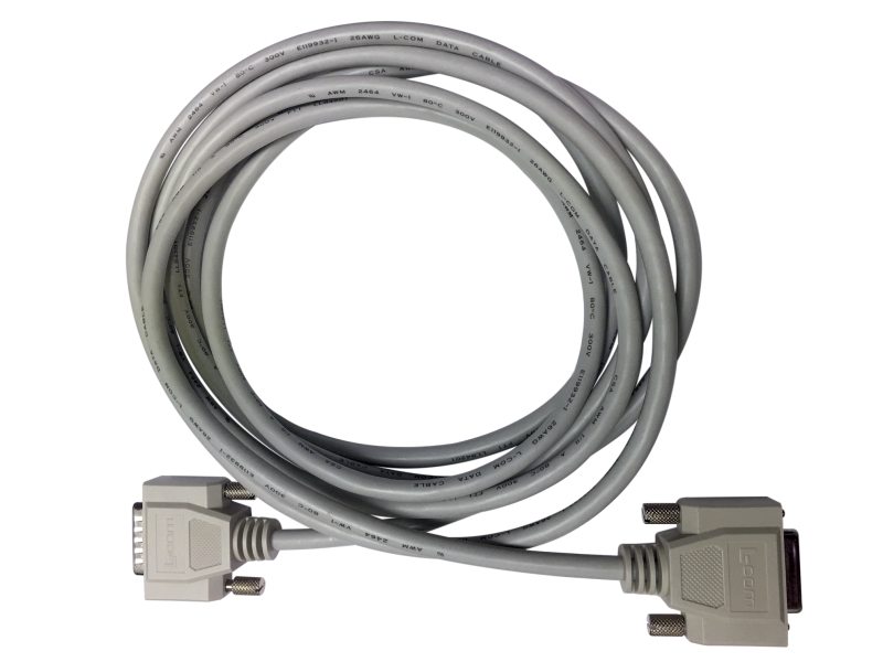
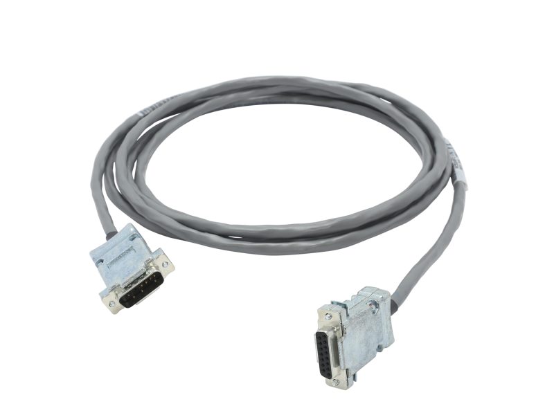
Accessories
| Compare | Description | Drawings, CAD & Specs | Avail. | Price | ||
|---|---|---|---|---|---|---|
 | CB147-12-10 | |||||
| CB147-1-10 | |||||
 | 100016744 | |||||
| 100016745 | |||||
| 100016746 | |||||
| CB259-5-10 | |||||
| 100019087 | |||||
| 100019088 | |||||
| 100019089 | |||||
| RCBDMFC-3-10 | |||||
 | RCBDMFC-1-10 | |||||
| RCB147-1-10 | |||||
| RCBDMFC-4-10 | |||||
| RCB147-12-10 | |||||
| RCB147-7-10 |
Resources
Literature
GM50A Metal Sealed Mass Flow Meter, 5 sccm - 50 slm(2.4 MB, PDF) GM51A 1.125 in. Metal Sealed, Digital Mass Flow Meter, 5 sccm - 50 slm(2.5 MB, PDF)
Application Notes
Manuals
G and I Series Mass Flow Controller/Meter Manual(2.2 MB, PDF) G-Series Mass Flow Controller/Meter DeviceNet™ Supplement(112.5 kB, PDF) G-Series Mass Flow Controller/Meter RS485 Supplement(149.3 kB, PDF) G and I-Series Mass Flow Controller/Meter Profibus Manual Supplement(86.9 kB, PDF) G-Series Mass Flow Controller/Meter PROFINET Communications Supplement(1 MB, PDF) G-Series/I-Series MFC Modbus Register Map and Specification(502.9 kB, PDF) G-Series MFC Web Browser Tutorial(5.6 MB, PDF)


