
IE1000A IP66 Rated Multi-gas, Multi-range Elastomer-sealed 500-1000 slm Mass Flow Meters
IE1000A IP66 Rated Multi-gas, Multi-range Elastomer-sealed 500-1000 slm Mass Flow Meters
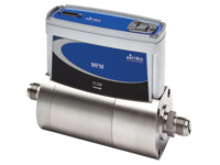
IE1000A mass flow meters are elastomer-sealed, multi-gas/multi-range MFMs designed for use in harsh environments where resistance to liquid and dust ingress are essential. Applications include those where "hose down" may be required, such as industrial glass production where moisture and particulates are present. With its IP66 rated enclosure, the IE1000A meets the stringent requirements of these aggressive environments.
The IE1000A can be ranged from 500 slm to 1000 slm (N2 equivalent). The multi-gas/multi-range capability, along with tight performance specifications for accuracy, allow users to minimize inventory of high flow MFM part numbers.
- IP66 rated enclosure provides protection against water & dust in harsh environments
- Tightly controlled flow accuracy of process gas improves process matching
- Multi-gas/multi-range capability reduces MFM inventory See All Features
Configuration Options
The following options are available for IE1000A Mass Flow Meters
Ordering Code Example: IE1000A013106TBR320
|
Configuration Option |
Option Code |
|---|---|
| IE1000A Mass Flow Meter | IE1000A |
Gas (Per Semi Standard E52-0703) |
|
| Helium (He): 700-1400 slm | 001 |
| Argon (Ar): 450-900 slm | 004 |
| Hydrogen (H2): 500-1000 slm | 007 |
| Nitrogen (N2): 500-1000 slm | 013 |
| Other Gas Options | See Here |
Flow Range Full Scale |
|
| 1000 slm (1,000,000 sccm) | 106 |
Fittings (compatible with) |
|
| 12 mm Swagelok | L |
| 0.5 in. tube compression | S |
| 0.75 in. compression | Z |
| 0.5 in. NPT female | M |
| 0.75 in. NPT female | N |
| 8 VCR male | T |
| 8 VCO male | D |
Connector |
|
| Profibus | 4 |
| PROFINET | 9 |
| 15 pin D (Analog 0-5 VDC I/O) | B |
| 15 pin D (4-20 mA I/O) | G |
Seal Materials |
|
| Viton® | V |
| Buna | B |
| Neoprene® | N |
| EPDM | E |
Device Type |
|
| Mass Flow Meter | 3 |
Firmware |
|
| MKS will ship firmware revision current to date | 20 |
* For gases not listed in the standard products gas table, please contact the MKS applications department for assistance.
** The Full Scale flow rate is designated by a 3 digit number. The first two digits represent the significant digits of the Full Scale flow rate separated by a decimal point. The third digit is the exponent of the power of ten. Example flow rate code: 255 is 2.5 x 10⁵ sccm or 250 slm; 105 is 1.0 x 10⁵ sccm or 100 slm
Specifications
- TypeMass Flow Meter (MFM)
- Full Scale Flow Range500-1000 slm (N2 equivalent)
- Measurement Range0.2-100% Full Scale (range on mech.)
- Fitting TypeCompatible with:
12 mm Swagelok
0.5 in. tube compression
0.75 in. compression
0.5 in. NPT female
0.75 in. NPT female
8 VCR male
8 VCO male - ConnectorProfibus
PROFINET
15 pin D (Analog 0-5 VDC I/O)
15 pin D (4-20 mA I/O) - Maximum Inlet Pressure150 psig
- Burst Pressure1500 psig
- Typical Accuracy±1% of Reading (with N2 calibration gas)
- Repeatability±0.5% of Reading
- Resolution0.1% of Full Scale
- Zero Temperature Coefficient<0.05% of Full Scale/°C
- Span Temperature Coefficient<0.08% of Reading/°C
- Inlet Pressure Coefficient<0.03% of Reading/psi
- Warm-up Time1 hour
- Operating Temperature10-50°C
- Storage Humidity0 to 95% relative humidity, non-condensing
- Storage Temperature-20° to 65°C (-4° to 149° F)
- External Leak Integrity<1 x 10⁻⁹
- Seal MaterialViton®
Buna
Neoprene®
EPDM - Wetted Materials316L S.S.
- Surface Finish20μ inch average Ra
- Enclosure RatingIP66
- Power Requirements15-24 VDC @ (<4 watts)
- Flow Input Output SignalVoltage (0-5 VDC)
Current (4-20 mA) - Analog I/O Connector15 pin Type ‘’D’’ male
- Weight<10.8 lbs (4.8 kg)
- ComplianceCE
Features
Communications
| Digital I/O | Profibus® | PROFINET® |
|---|---|---|
| Input Power Required | +15 to +24 VDC (<2 watts) | +24 VDC (<3 watts) |
| Connector | 9 pin Type D male (power) 9 pin Type D female (comm.) |
2 x RJ-45 (comm.) male M8 male 5 pin (power) |
| Data Rate Switch/Selection | No switch Set data rate via Profibus |
No switch |
| Comm. Rate(s) | 9.6 Kbps to 12 Mbps | 100 Mbps |
| MAC ID Switches/Addresses | 2 switches, 10 positions | n/a |
| Network Size | Up to 99 nodes | n/a |
| Visual Indicators | LED Comm (green/red) LED Error (green/red) |
LED Maint (amber) LED BUS Fault (red) LED Ready (green) LED Sys Fault (red) |
| Compliance | CE | CE |
Multi-gas/Multi-range Capable
The multi-gas/multi-range capability, along with tight performance specifications for accuracy, allow users to minimize inventory of high flow MFM part numbers. The multi-gas/multi-range feature (along with other custom controls) is accessed through the MFM embedded diagnostic interface, that requires no special software or hardware to operate. A standard Ethernet cable and JAVA-enabled HTML browser, widely available, are all the tools needed. The critical gas parameters for typical high flow rate gases are already stored on the device. Configuring the device is simply a matter of selecting the gas from a drop down menu and specifying the desired full scale flow range. The diagnostic interface also allows the user to perform routine device health checks, plot flow, and store operating data for off-line analysis.
Accessories
| Compare | Description | Drawings, CAD & Specs | Avail. | Price | ||
|---|---|---|---|---|---|---|
 | CB147-12-10Cable, Mass Flow Controller, DB9, 10 ft. | |||||
| CB259-5-10Cable, Mass Flow Controller, 246, 247 or 660 Controllers, DB15, 10 ft. | |||||
| CB147-1-10Cable, Mass Flow Controller, PR4000, 146, 167, 186 or 647 Controllers, DB15, 10 ft. |
Resources
Literature
Application Notes
Manuals
G and I Series Mass Flow Controller/Meter Manual(2.2 MB, PDF) G and I-Series Mass Flow Controller/Meter Profibus Manual Supplement(86.9 kB, PDF) G-Series/I-Series MFC Modbus Register Map and Specification(502.9 kB, PDF) G-Series MFC Web Browser Tutorial(5.6 MB, PDF)
