
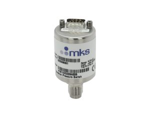
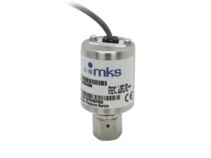
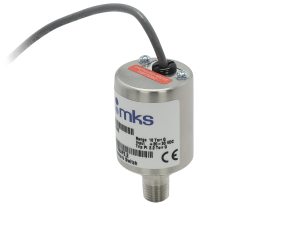
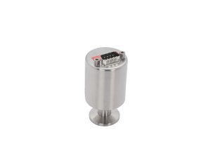
Baratron® 41C Single-End Gauge Pressure Switches
Baratron® 41C Single-End Gauge Pressure Switches
The 41C Single-end 10 - 26,000 Torr Pressure Switch offers accurate and reliable protection for vacuum vacuum/pressure processes. Designed for applications where a DC signal output is not required, these switches provide relay outputs that are readily interfaced with alarms, valve actuators, computers, process controllers, load locks and other protection devices. The 41C is referenced to atmospheric pressure. The trip point on can be set to trip above, below (reverse calibration), or exactly at current atmospheric pressure.
- Single-end configuration referenced to atmospheric pressure
- Superb set point accuracy with low hysteresis
- All-metal, all-welded construction exposes only stainless steel and Inconel® for corrosion resistance
- Switch relay can be set to energize above or below set point for fail-safe operation
- High reliability reduces downtime See All Features
| Compare | Description | Drawings, CAD & Specs | Avail. | Price | ||
|---|---|---|---|---|---|---|
 | 41C11DCA2BA003Pressure Switch, Single-ended, 10 Torr, 4VCR Male, 9-Pin Type D Male, Referenced to Atmospheric Pressure | |||||
 | 41C11DCD2BF003Pressure Switch, Single-ended, 10 Torr, 4 VCR Female, Flying Leads, Referenced to Atmospheric Pressure | |||||
 | 41C11TFB2AF2.2Pressure Switch, Single-ended, 10 Torr, 0.25 in. NPT Male, Flying Leads, Referenced to Atmospheric Pressure | |||||
 | 41C13DGA2AA040Pressure Switch, Single-ended, 1000 Torr, NW16 ISO-KF, 9-Pin Type D Male, Referenced to Atmospheric Pressure |
Configuration Options
The following options are available for the 41C Baratron® Single-End Pressure Switch.
Ordering Code Example: 41C11TCA1AA005
| Configuration Option | Option Code |
|---|---|
| 41C Single-End Pressure Switch | 41C |
Full Scale Ranges Available (Contact Applications Engineering for other engineering units) |
|
| 10 Torr | 11T |
| 30 Torr | 31T |
| 100 Torr | 12T |
| 500 Torr | 52T |
| 1000 Torr | 13T |
| 20 psi | 21P |
| 50 psi | 51P |
| 100 psi | 12P |
| 250 psi | RDP |
| 500 psi | 52P |
| 10 Torr (reverse calibration) | 11D |
| 30 Torr (reverse calibration) | 31D |
| 100 Torr (reverse calibration) | 12D |
| 500 Torr (reverse calibration) | 52D |
| 1000 Torr (reverse calibration) | 13D |
| 20 psi (reverse calibration) | 21C |
| 50 psi (reverse calibration) | 51C |
| 100 psi (reverse calibration) | 12C |
| 250 psi (reverse calibration) | RDC |
| 500 psi (reverse calibration) | 52C |
Fittings |
|
| NW16 ISO-KF | GA |
| 0.125 in. NPT male | FE |
| 0.25 in. NPT male | FB |
| 4 VCR fixed male | CA |
| 4 VCR female | CD |
Input Voltage |
|
| 10-20 VDC | 1 |
| 20-30 VDC | 2 |
Relay Mode |
|
| Energizes with pressure above the set point | A |
| Energizes with pressure below the set point | B |
Connector |
|
| 9-pin Type "D" male | A |
| Flying leads - 2 ft. shielded cable | F |
Trip Point* |
|
| Three digit value (in same units as Full Scale ranges) | xxx |
* For a trip point of 000 (atmospheric pressure), use a reverse calibration Full Scale range code
Specifications
- TypePressure Switch
- ConfigurationSingle-Ended
- Accuracy±0.5% of Full Scale (± temperature coefficient)
- Trip Point Range5% to 100% of Full Scale
- Trip Point Dead Band±3% of Full Scale
- Response Time<20 msec
- Internal Volume3.3 cc
- Temperature Coefficient±0.07% of Full Scale/°C
- Materials Exposed to Process GasesInconel and 316L stainless steel
- Overpressure2 x Full Scale or 45 psia, whichever is greater
- OutputsElectromechanical relay - SPDT (isolated) contacts rated up to 1 Amp @ 30 VDC resistive.
- Power Requirements20-30 VDC
- Ambient Operating Temperature0-50°C
- ComplianceCE, UL recognized* (cULus E520864), EN/IEC CB Approved to all National Deviations *standard MKS part numbers only
Features
Baratron® Capacitance Manometer Technology
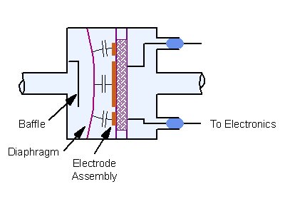
Capacitance manometers are electro-mechanical gauges that can measure both pressure and vacuum. The capacitance gauge translates a pressure-modulated movement in a thin diaphragm into an electrical signal proportional to the pressure. The pressure sensor is the thin diaphragm that is exposed to the pressure or vacuum being measured via the inlet tube. An electrode is mounted in the reference cavity behind the diaphragm. Pressure differences between the process and the reference cavity deflect the diaphragm slightly, changing the distance between it and the electrode. Variations in this distance produce variations in the capacitance between the diaphragm and the electrode creating an electrical signal that is proportional to the pressure change. Since differences in the capacitance signal are produced by physical changes within the manometer and not by changes in the gas properties, pressure measurements by the capacitance manometer are independent of the composition of the gas being measured.
Referenced to Atmospheric Pressure
The 41 and 42 vacuum/pressure switches are referenced to atmospheric pressure. They are often used to ensure a loadlock pressure has equilibrated to local atmospheric pressure before opening the door. The trip point on MKS’ atmospheric switches can be set to trip above, below (reverse calibration), or exactly at current atmospheric pressure.
Factory Set Trip Point
The relay trip point is factory set from 5% to 100% of the Full Scale pressure range. This means there is no need for personnel to adjust the set point and no safety concerns from an erroneously adjusted set point.
Fail-Safe Relay Operation
The relay mode on 41, 42, 51, and 52 switches can be set to either energize above or below the set point. If the unit loses power, the relay switches to the Normally Closed position. The user can indicate whether the Normally Closed position is above or below the set point. Using Energize Above the set point as an example, the relay is in the Normally Open position when the pressure is higher than the trip point and Normally Closed when the pressure is below the trip point. The scenario is reversed for Energize Below the set point option. In vacuum systems, the fail-safe operation is if the system loses power causing the relay to de-energize, the relay is in the same state as the high pressure condition. Therefore, most vacuum systems require the relay energize with pressure decreasing or below the set point.
The 41B, 42B, 51B and 52B Vacuum and Atmospheric Pressure Switches provide increased accuracy over mechanical type switches, thereby providing tighter control and repeatability of process, improving throughput and yield.
9-pin Type “D” Pinouts
| Pin | Description |
|---|---|
| 1 | Power Return (-) |
| 2 | Power Input (+) |
| 3 | Relay NO Contact |
| 4 | Relay Common |
| 5 | Relay NC Contact |
| 6 | Unused |
| 7 | Unused |
| 8 | Unused |
| 9 | Chassis Ground |
Flying Lead Wiring
| Wire | Description |
|---|---|
| Red | Power Input (+) |
| Black | Power Return (-) |
| Green | Relay NO Contact |
| White | Relay Common |
| Orange | Relay NC Contact |
| Bare Wire | Chassis Ground |
Resources
Literature
41C, 42C, 51C, 52C Pressure Switches(2 MB, PDF)
Manuals
MKS 41C, 42C, 51C, & 52C Pressure Switches Manual (705.4 kB, PDF) 41, 42, 51, 52 Vacuum/Pressure Switch Pin-outs(23.6 kB, PDF)